Crossing Simulation
In this tutorial you will learn how to configure a basic simulation scenario with netedit from scratch. The scenario consists of crossing with interacting cars and pedestrians. We will define the simulation network and the demand for vehicle and person flows. First, you will run a simulation with the default pedestrian model of SUMO (striping model). Then you will switch to the JuPedSim model and inspect the results. At the end of this tutorial, you can find videos of the simulation results for both models.
You can find the resulting configuration files for this tutorial here.
Note
If you made a mistake press Ctrl + Z to undo the last step.
The message window at the bottom of netedit informs you about warnings and errors. For this tutorial, the window was hidden.
Setting up the Network#
Open netedit and create a new network by clicking on File > New Network. Now you are in the Network supermode and can draw the roads for the crossing. By default the Edge mode is activated. To draw two-way roads enable the Edge opposite direction on the right side of the toolbar. Then you can draw the edges (roads) in the editor.
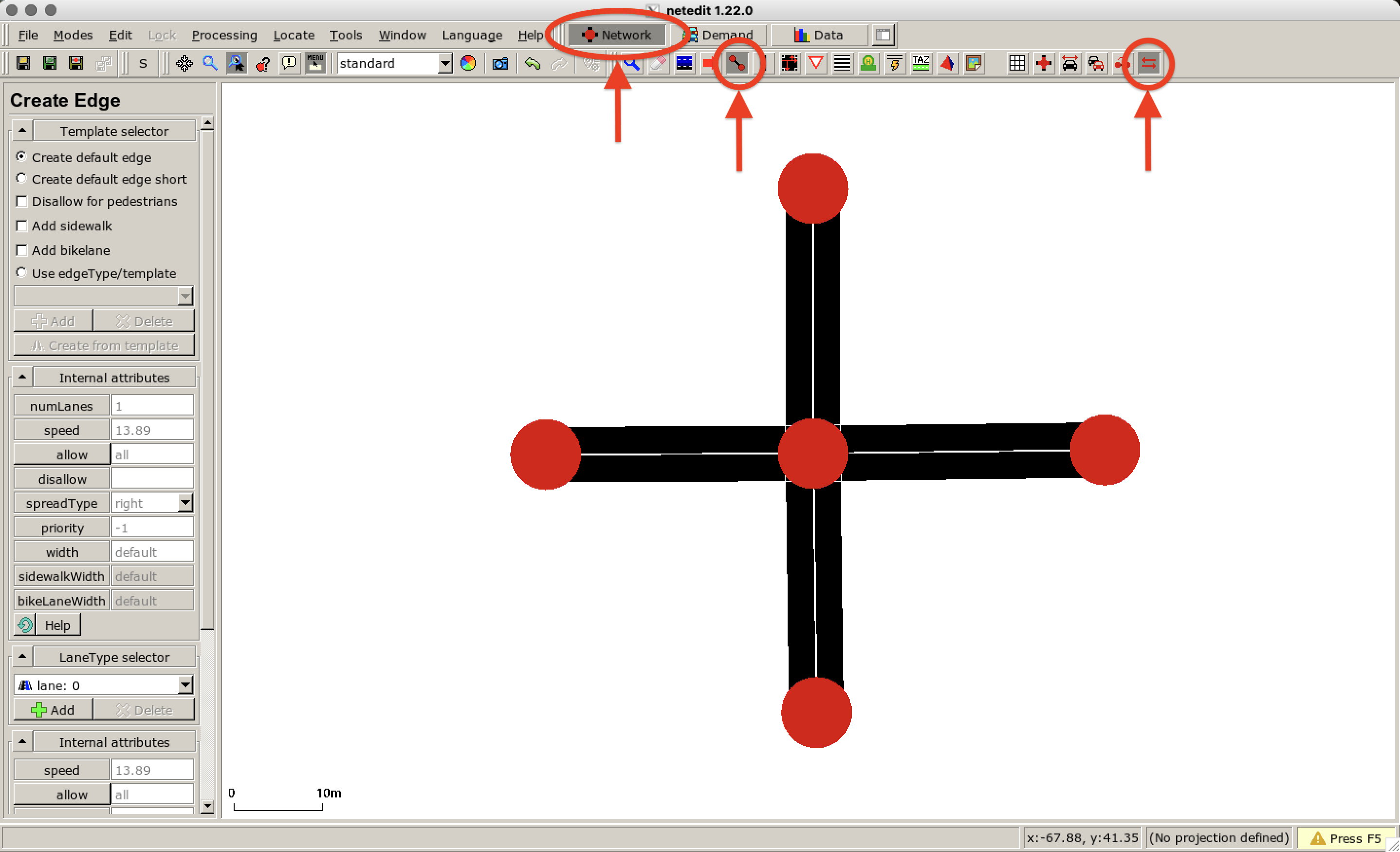
Make sure that the edges are connected by a node in the center so that a crossing can be generated. To learn more about the SUMO road network we refer to this website.
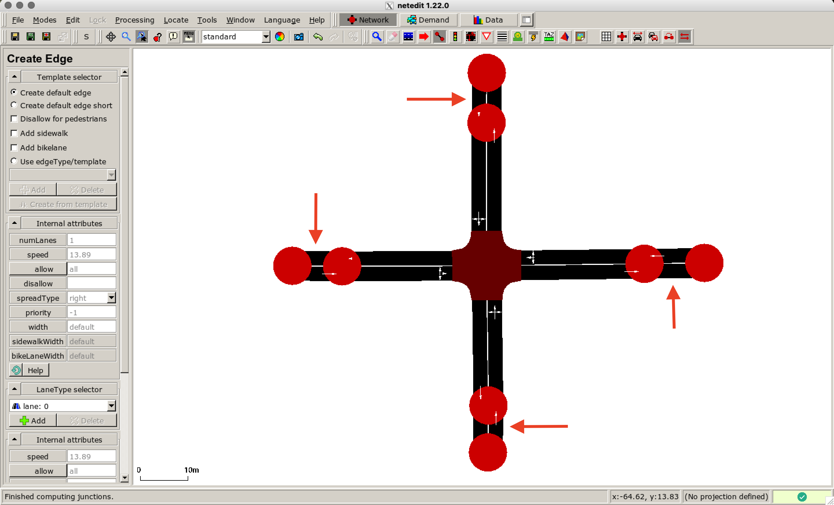
As pedestrians are spawned distributed along an edge we define small edges at the end of the roads of interest. In this way, we reduce the effects of the initial conditions and the pedestrians are already in motion when they enter the network defined above. To compute junctions press F5 or click Processing > Compute Junctions.
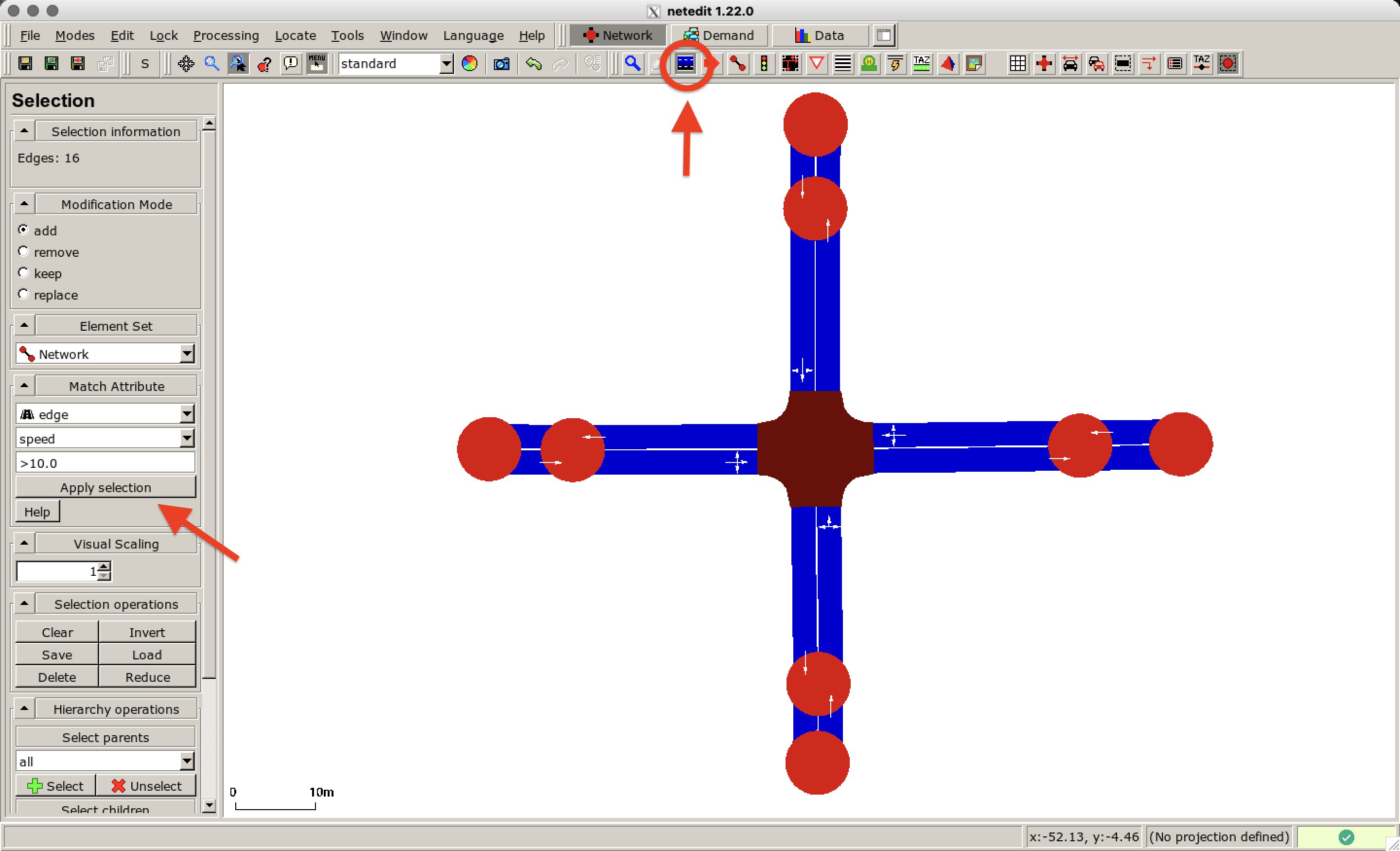
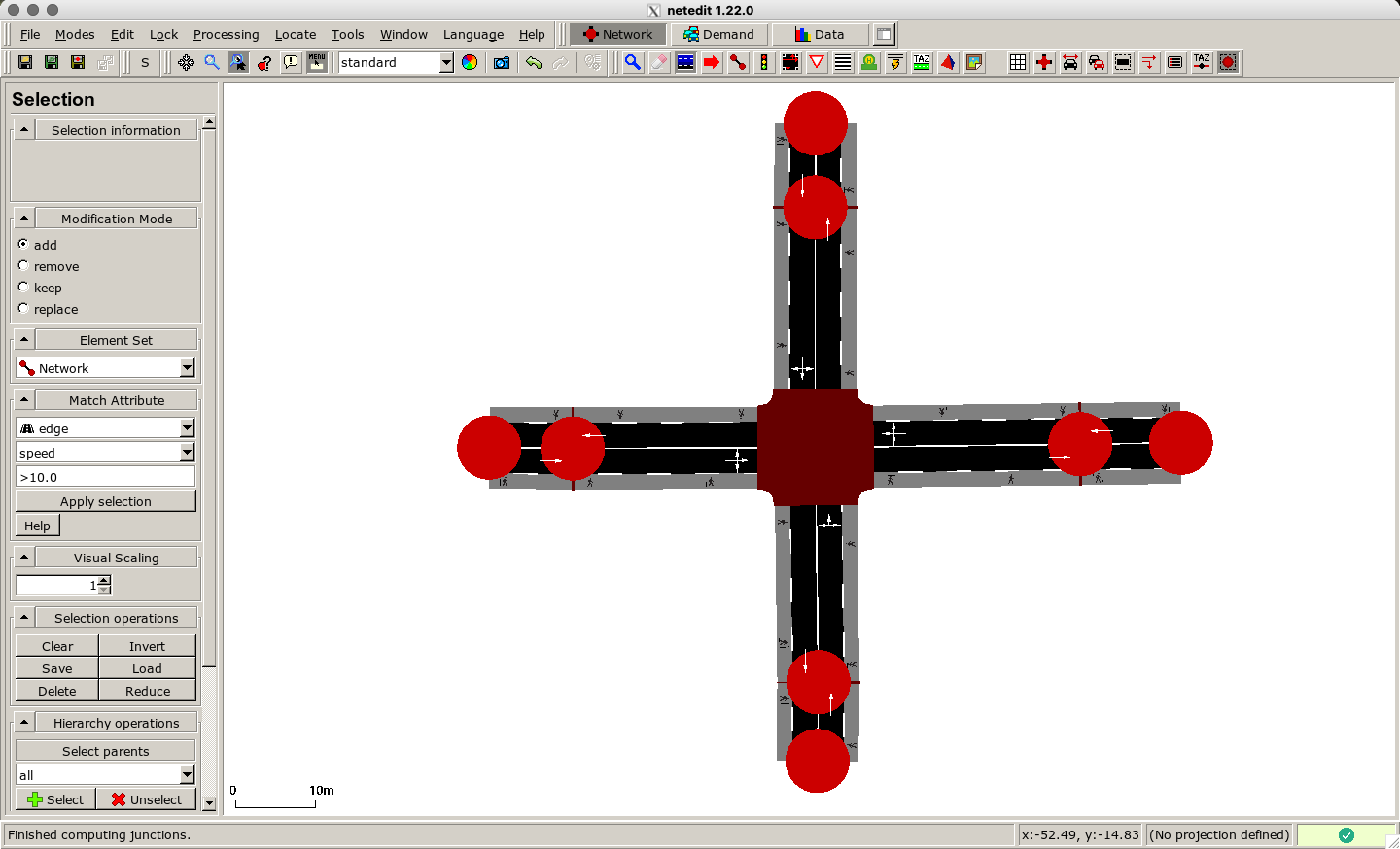
Now we add sidewalks for the pedestrians to our network. For this, we enable the Select Mode. In the selection menu on the left choose Apply selection for the specified match attributes. The selected edges are highlighted in blue.
Then right click on the selected edges Lane operations > Add restricted lane > Sidewalk and confirm the operation as shown here:
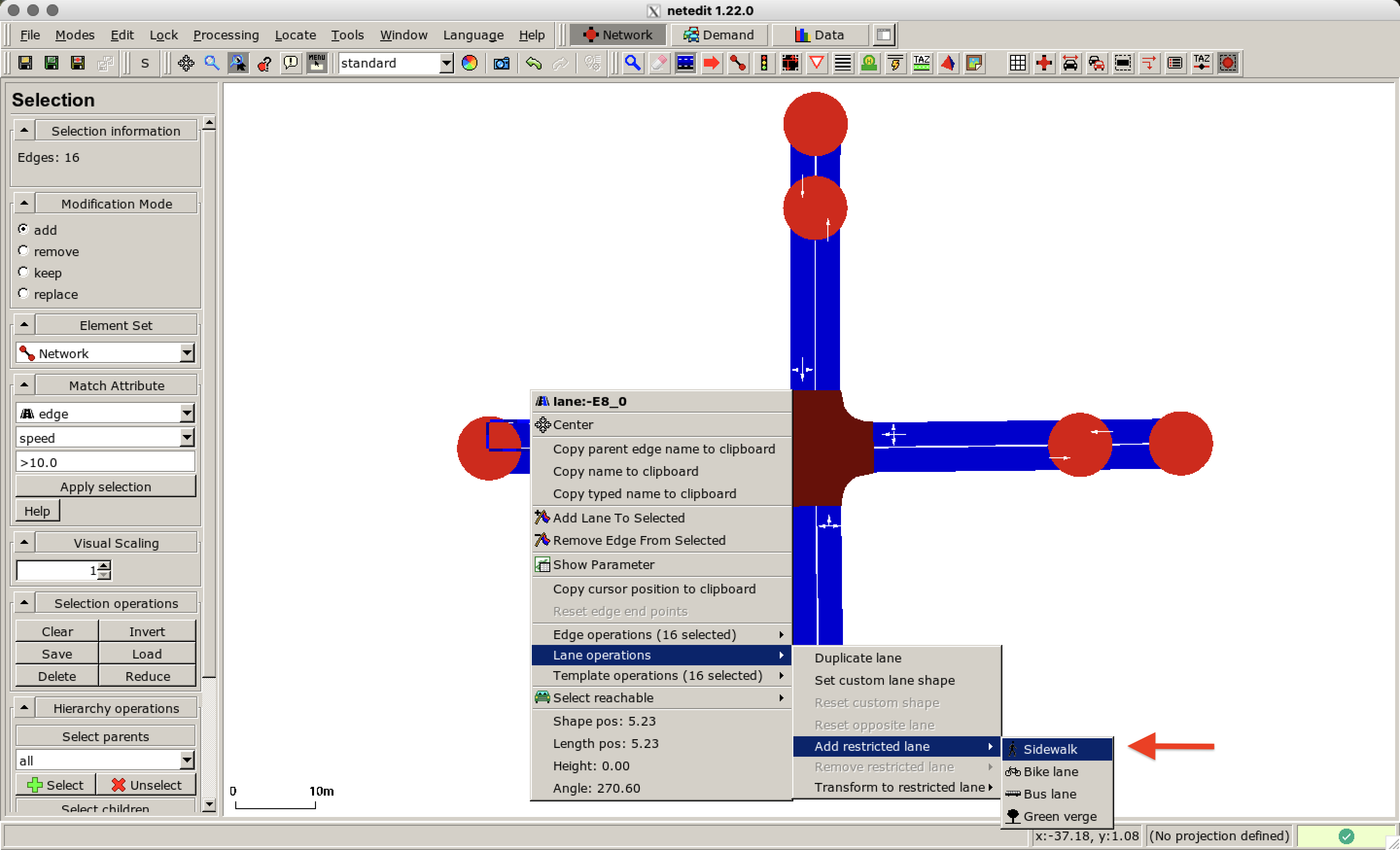
For each road a sidewalk is created. Clear the selection by pressing ESC and compute the junctions again (press F5). The network should look like this:
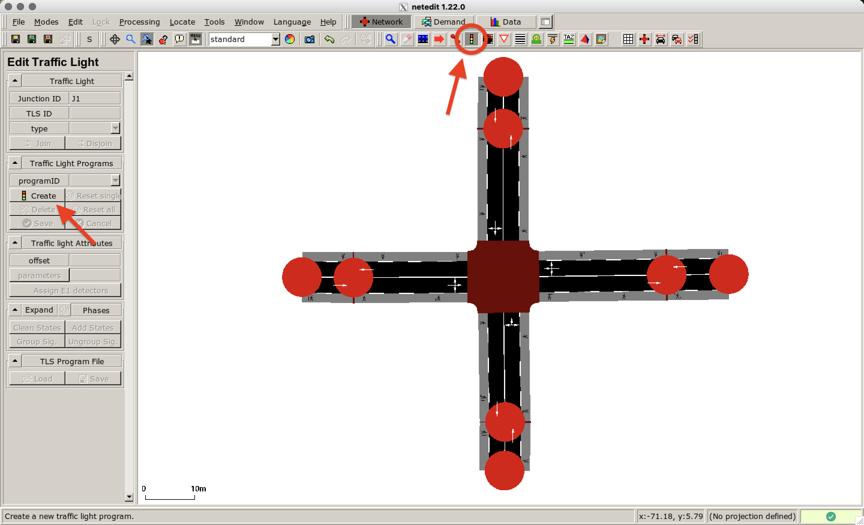
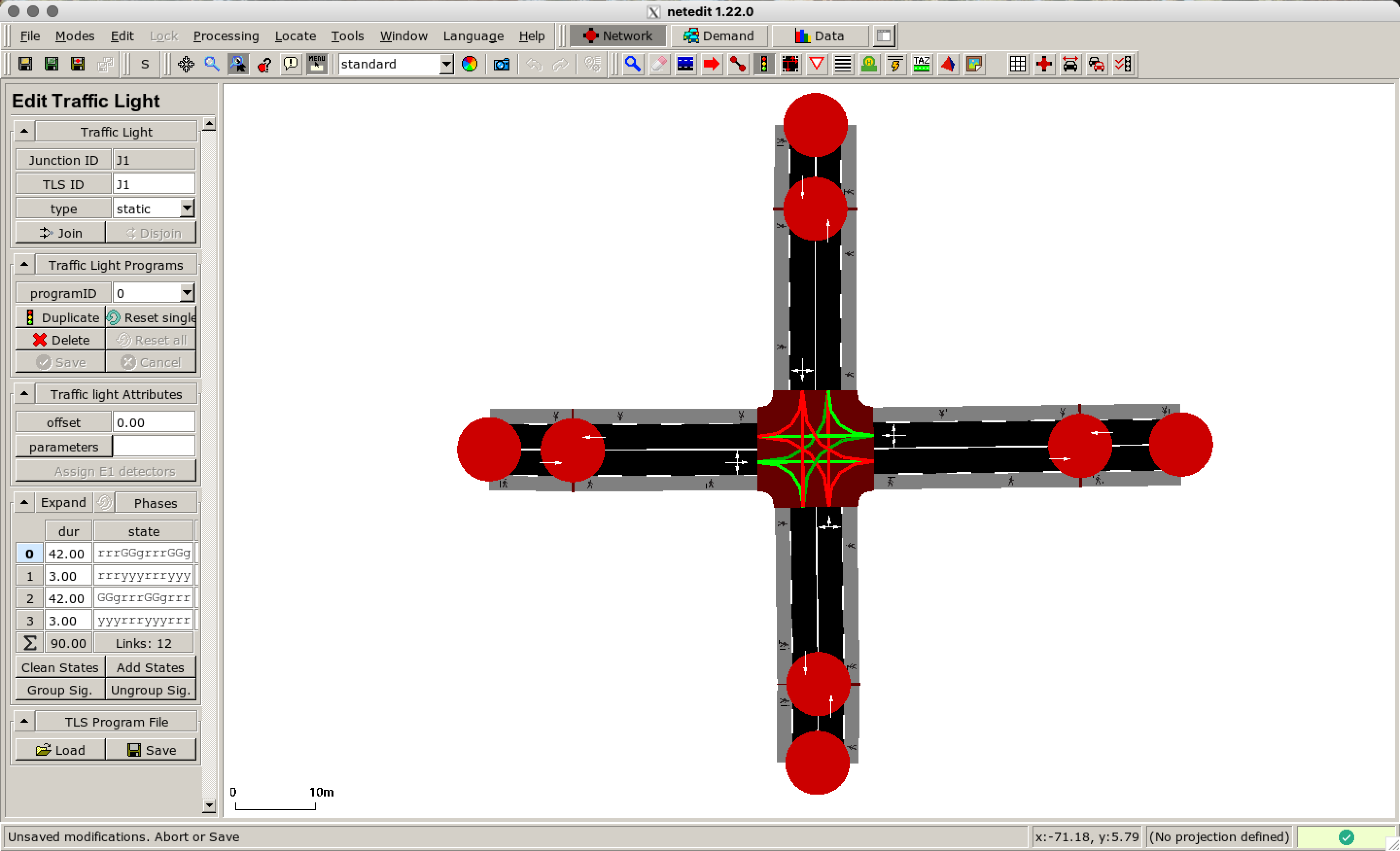
Now we add a traffic light. Switch to Traffic light mode and select the junction in the middle of the network. Then click on Create in the left menu.
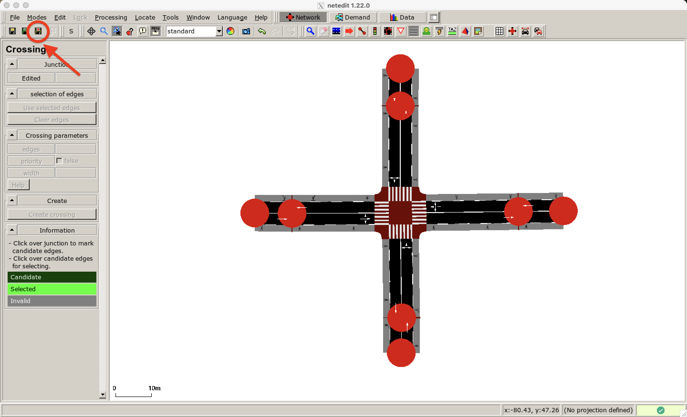
Now we configure the crossing options for pedestrians. Enable the Crossing mode and click on the junction. Select the pair of roads that should be connected by a crosswalk and press Enter. Possible candidates are highlighted in dark green. Once you have selected a candidate (light green) the matching one is restricted to the neighbored lane.
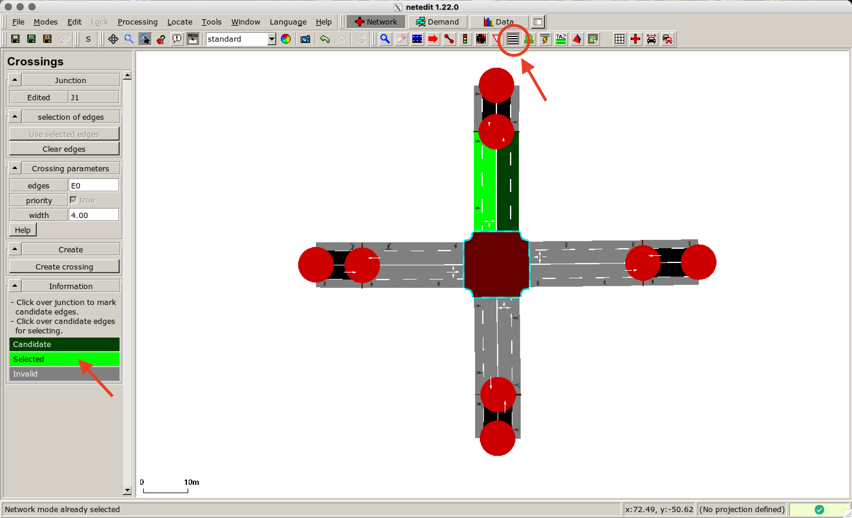
In this example, pedestrians are allowed to cross the junction on all roads. So you have to repeat this process for the three remaining roads.
You have finished the configuration of the network. Save the network file by clicking Save network in the toolbar on the left. In this example, the file is named crossing.net.xml.
Setting up the Demand#
Next, we configure the flow of cars and pedestrians at the border of the defined crossing.
Vehicle Flow#
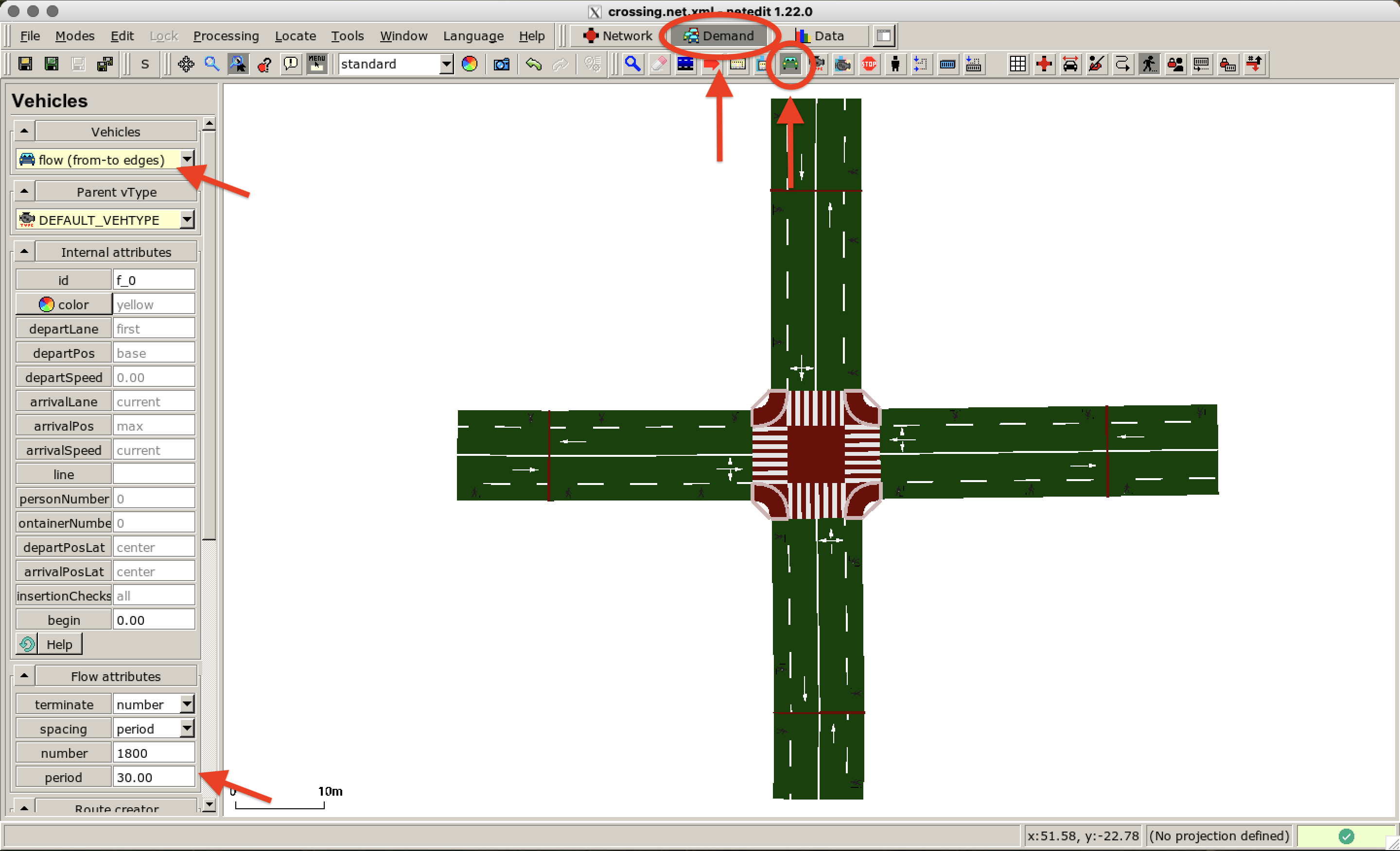
We start with the vehicles. Switch to the Demand supermode and enable the Vehicle mode. As we want to create a flow of vehicles, you need to choose the option flow (from-to edges) at the top of the menu on the left. You can define properties of the flow when you scroll down the menu. We define that a car should appear every 30 seconds.
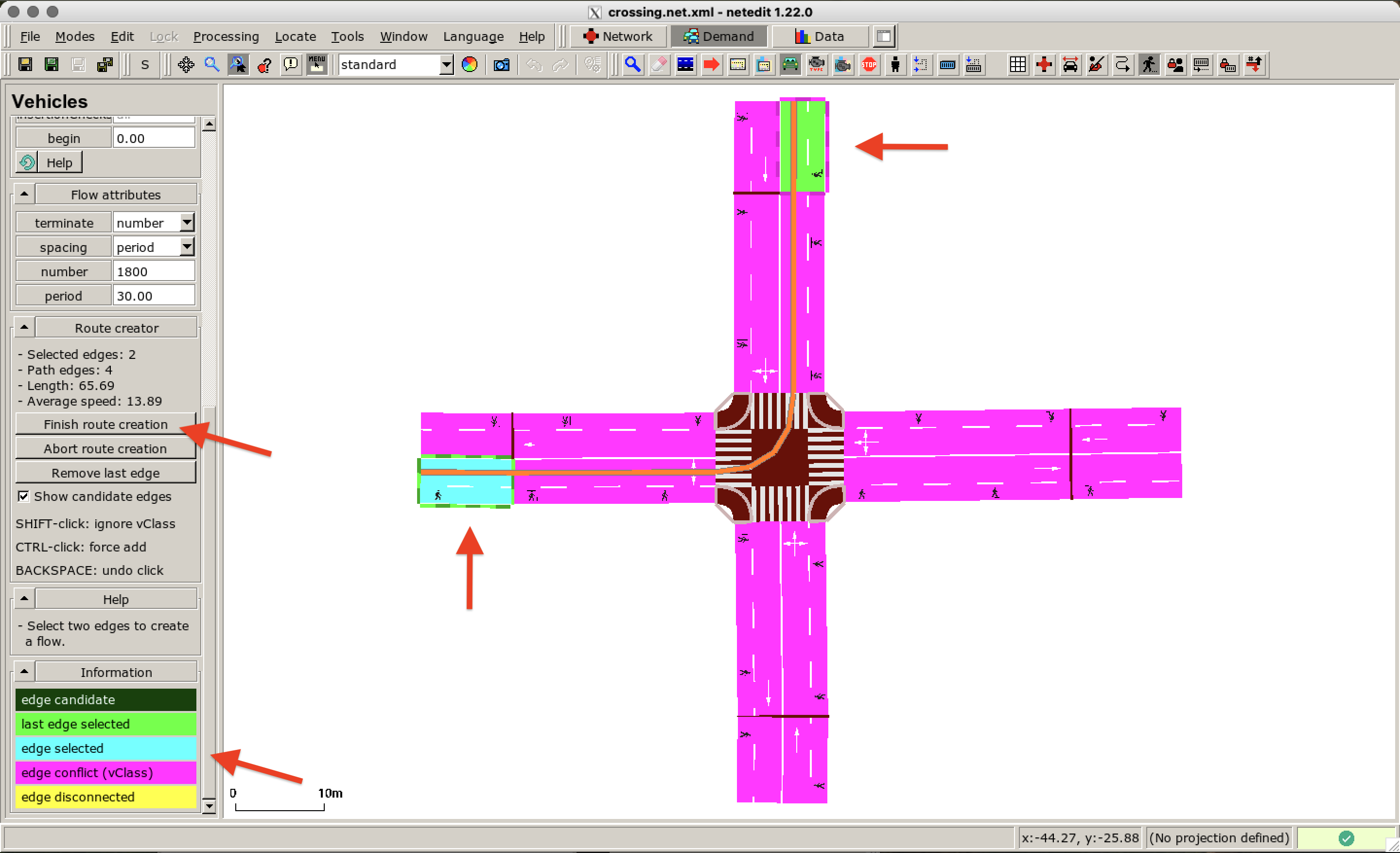
Now you can define the route for that flow by clicking on the edge where the flow should start. If you scroll down on the left, you can see information on the coloring of the edges in the defined network. Select the edges you want to connect and click on Finish route creation in the menu on the left.
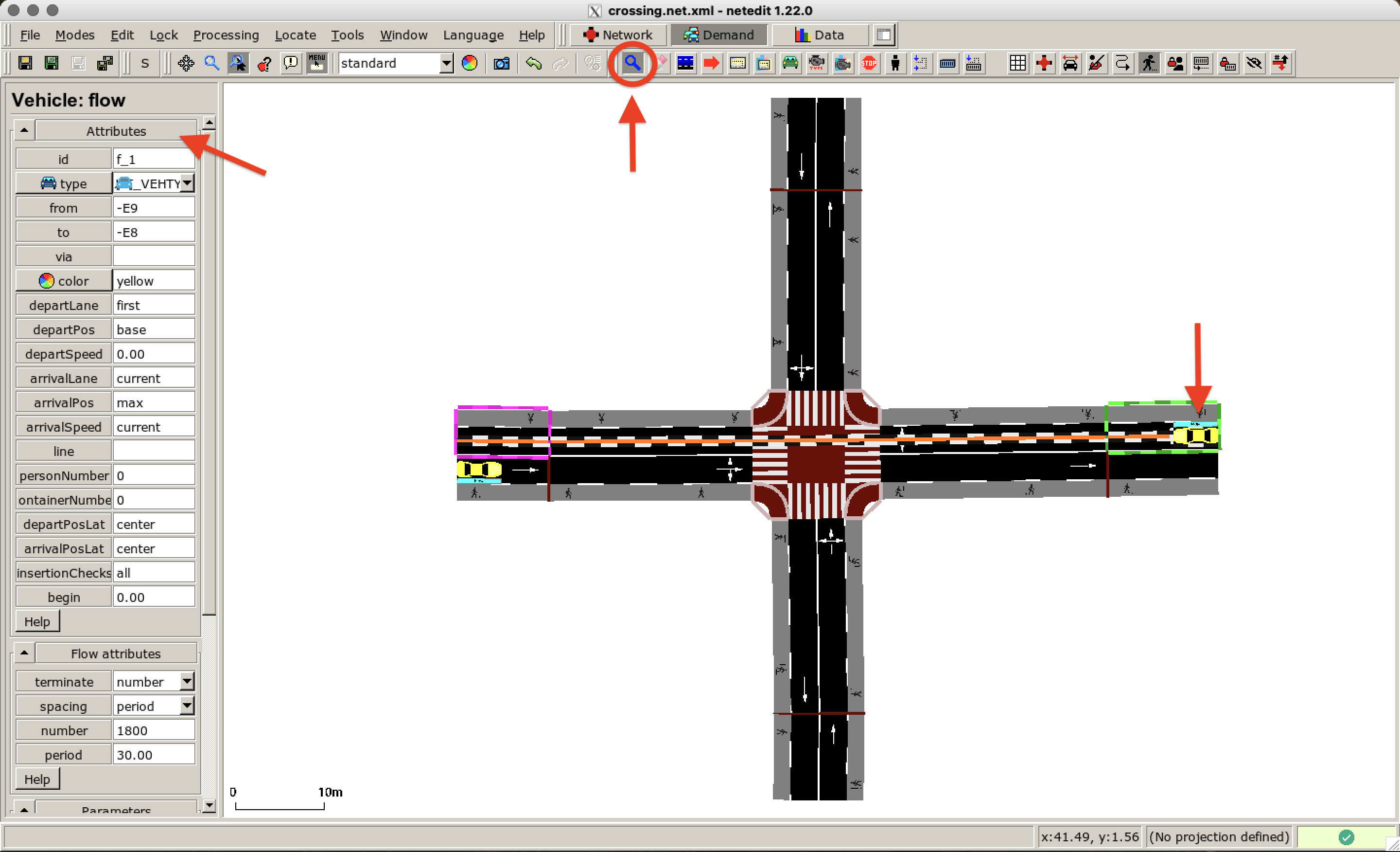
We create a second flow and define a route starting from a different edge. By default, this flow has the same properties as the previously defined flow - we keep the same attributes. We switch to Inspect mode and click on a vehicle to check its attributes and route. This way you can modify the attributes after creating elements.
Person Flow#
Next, we add pedestrian flows to the scenario. Click on the Person mode and choose the personFlow on the top of the menu on the left. We choose red as the color for the first flow. For departPos type in random so that the pedestrians are distributed on different positions along the edge. The spawning period is set to 4 seconds.
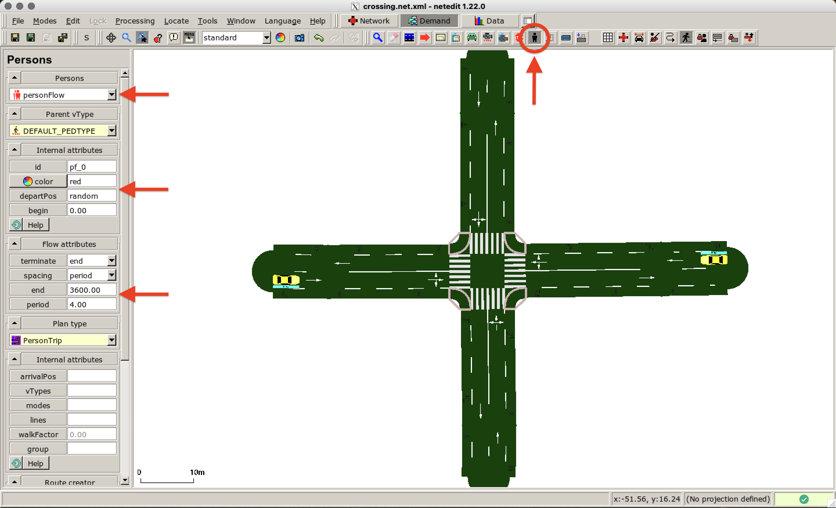
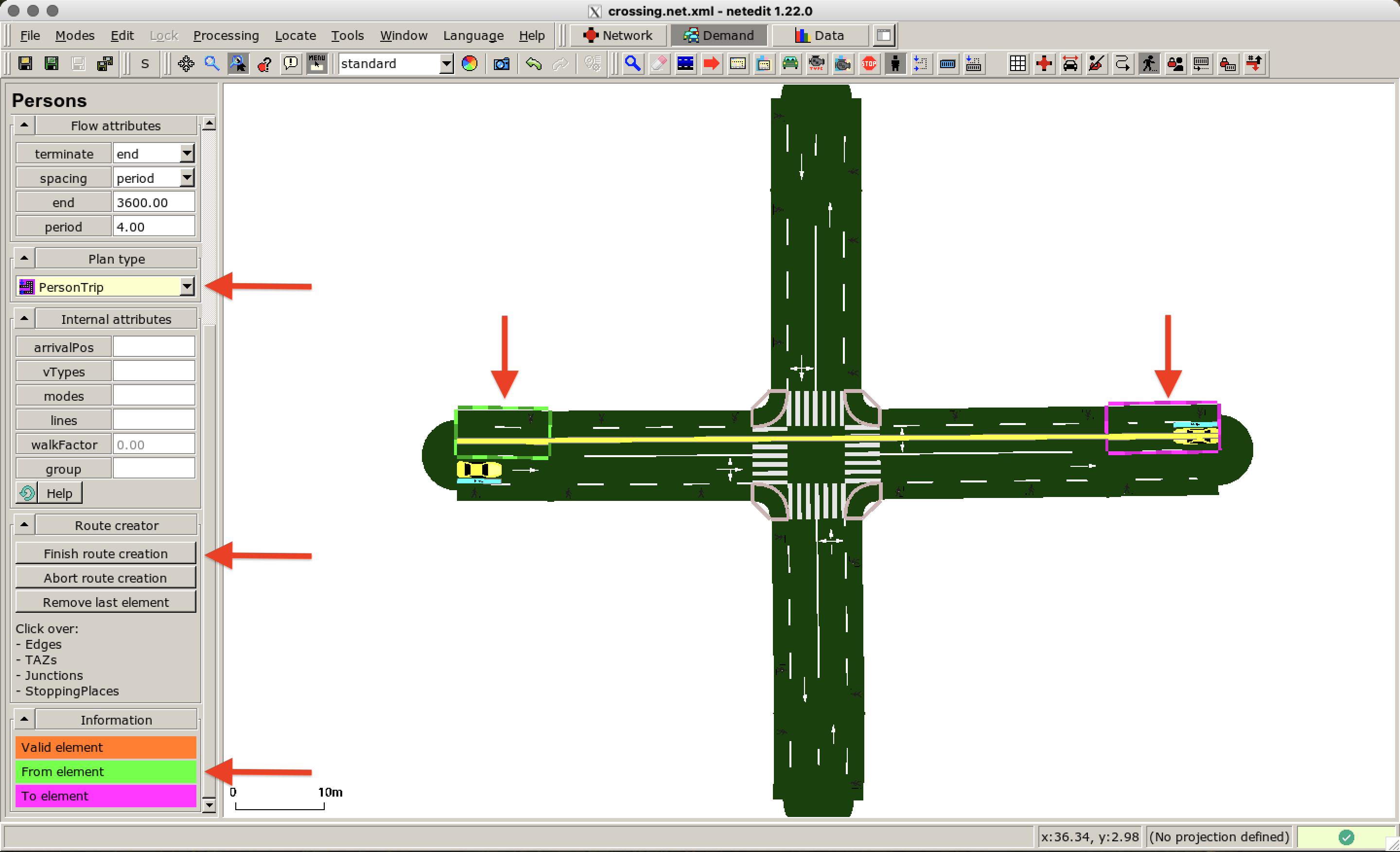
As plan type we use the default PersonTrip. Scroll down to the Route creator in the menu on the left. Now we can plan the route as for the vehicle flow. Click on an edge where the pedestrians should be spawned and click on the destination edge. Do not forget to click on Finish route creation.
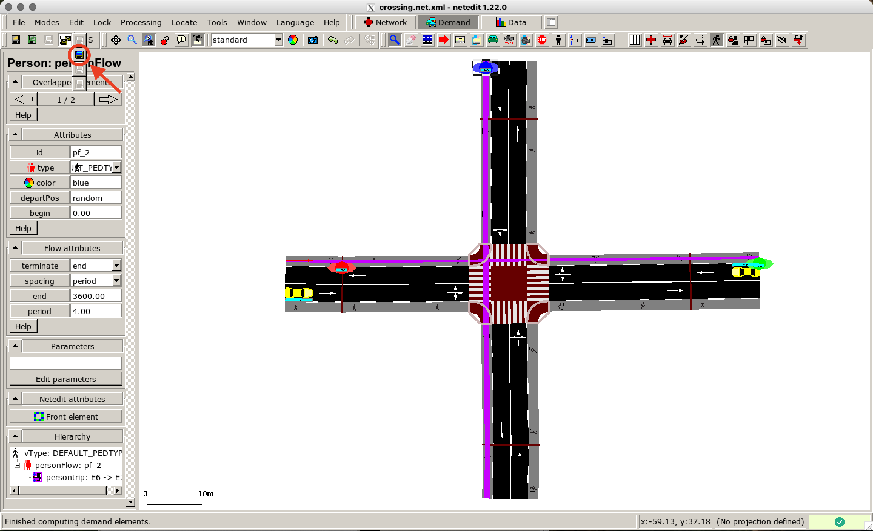
We add more flows starting from different edges. In this example, we define two flows that are moving towards each other (red and green) and one additional flow, that is crossing from above (blue). We save the demand file named as crossing.rou.xml.
Run with Striping Model#
Next, we start the simulation with the default settings. To do so open the simulation configuration in sumo-gui as shown here:
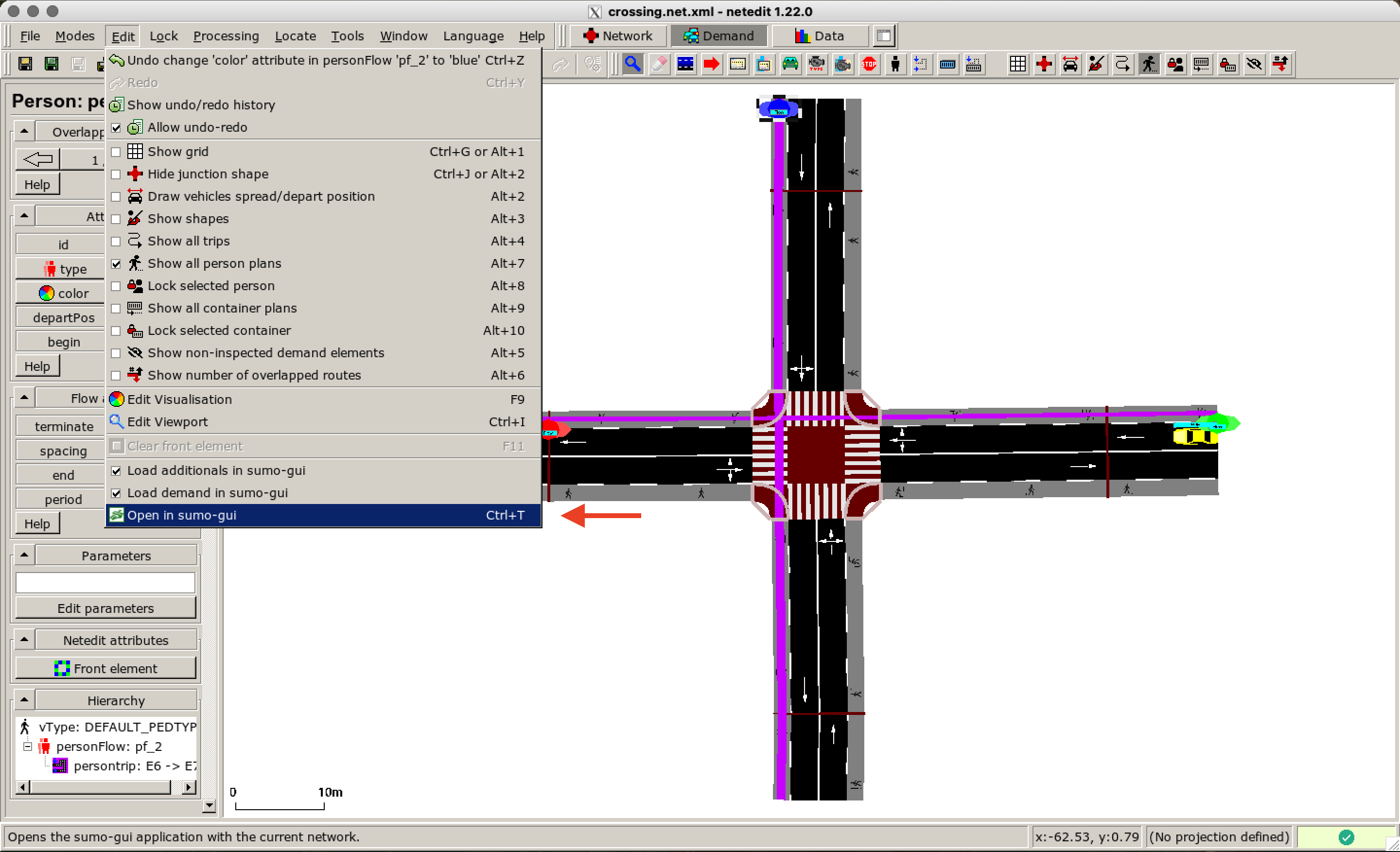
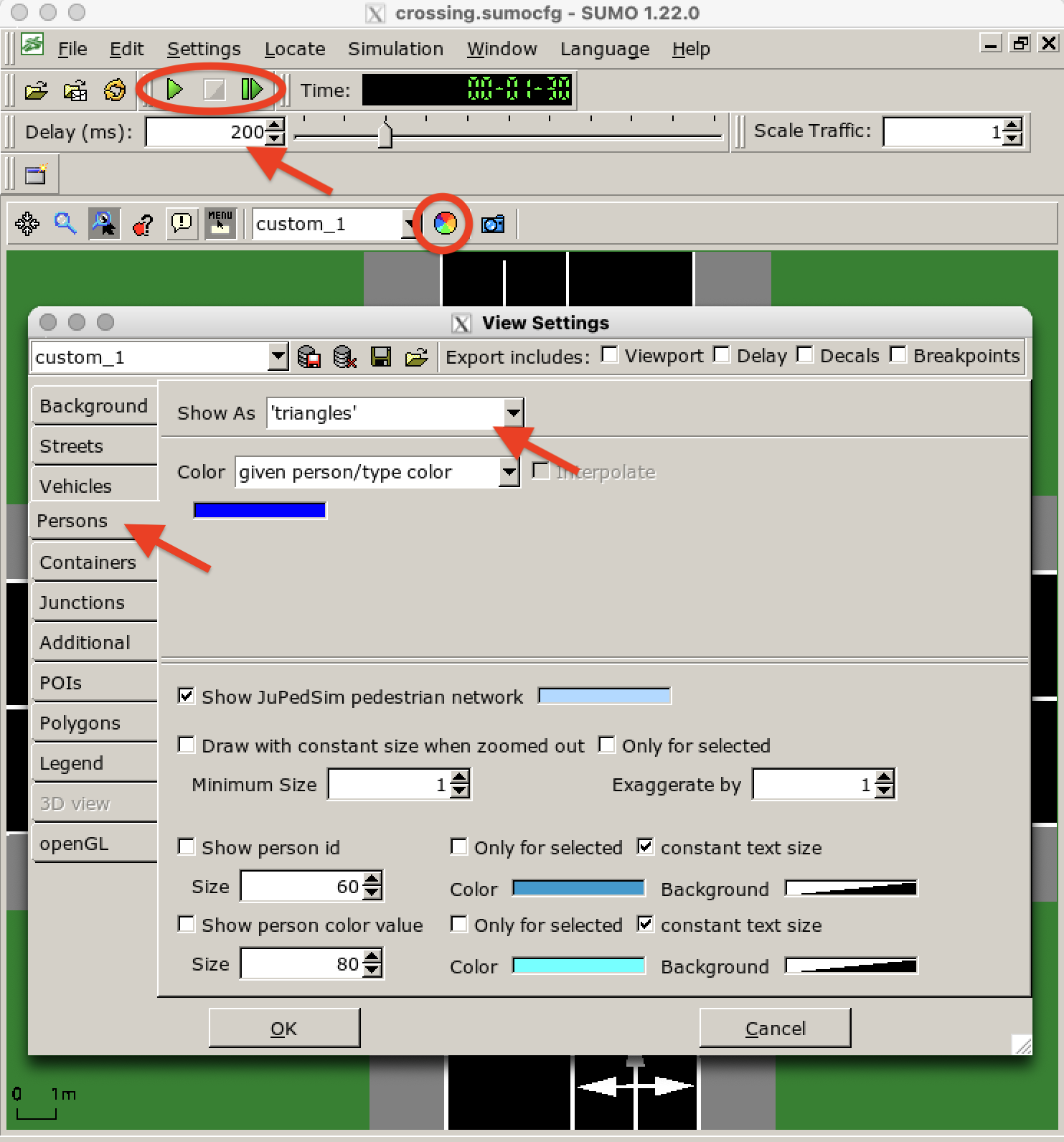
netedit asks for saving the sumoconfig file. After saving the file as crossing.sumocfg, a new window in sumo-gui is opened. Before pressing Run increase the Delay (as the simulation is performed very quickly) and adapt the visualization as you wish. We choose triangles as a visualization for the pedestrians. This option can be found by clicking on Edit Coloring Schemes (color wheel) and then go to Persons.
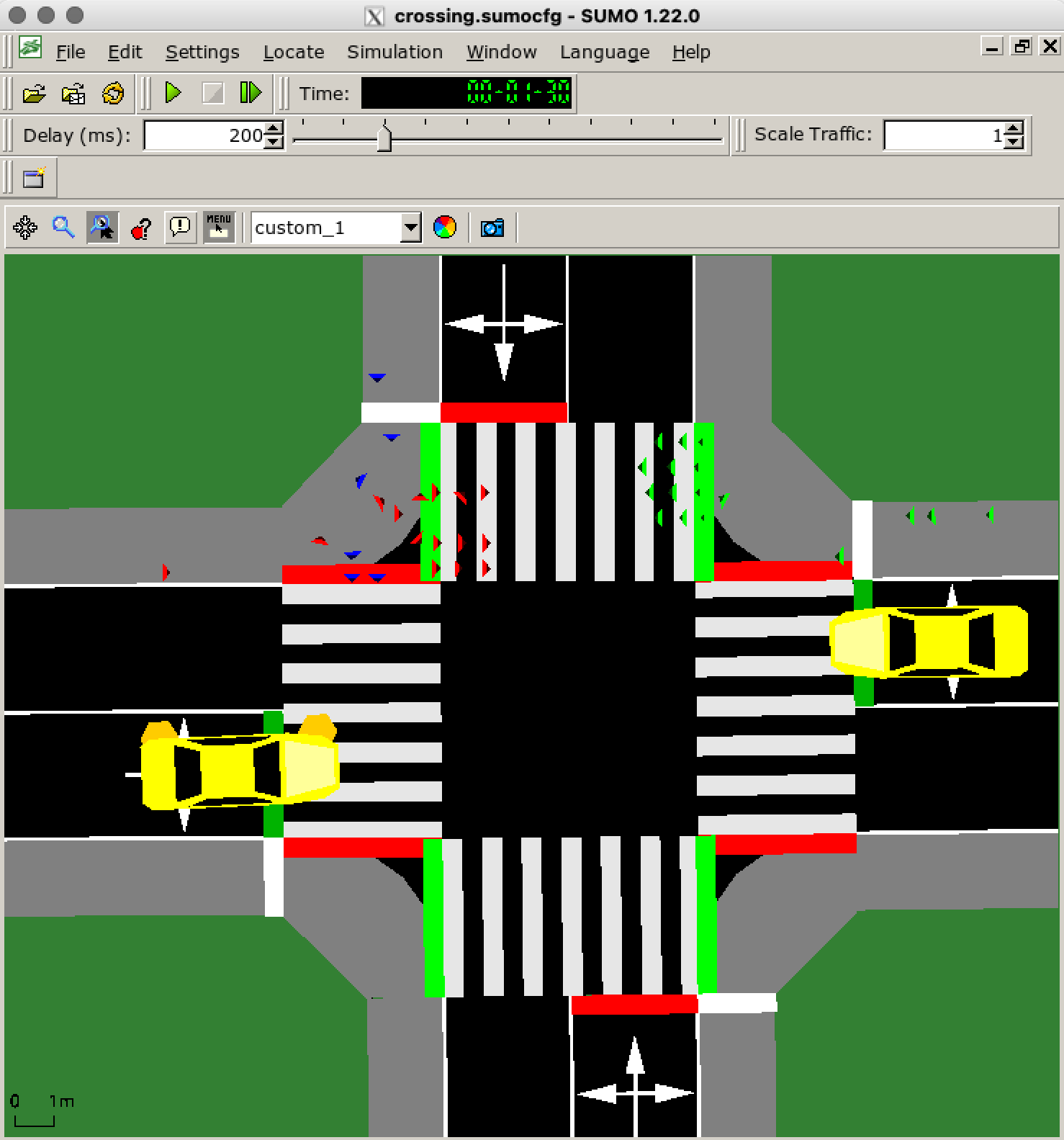
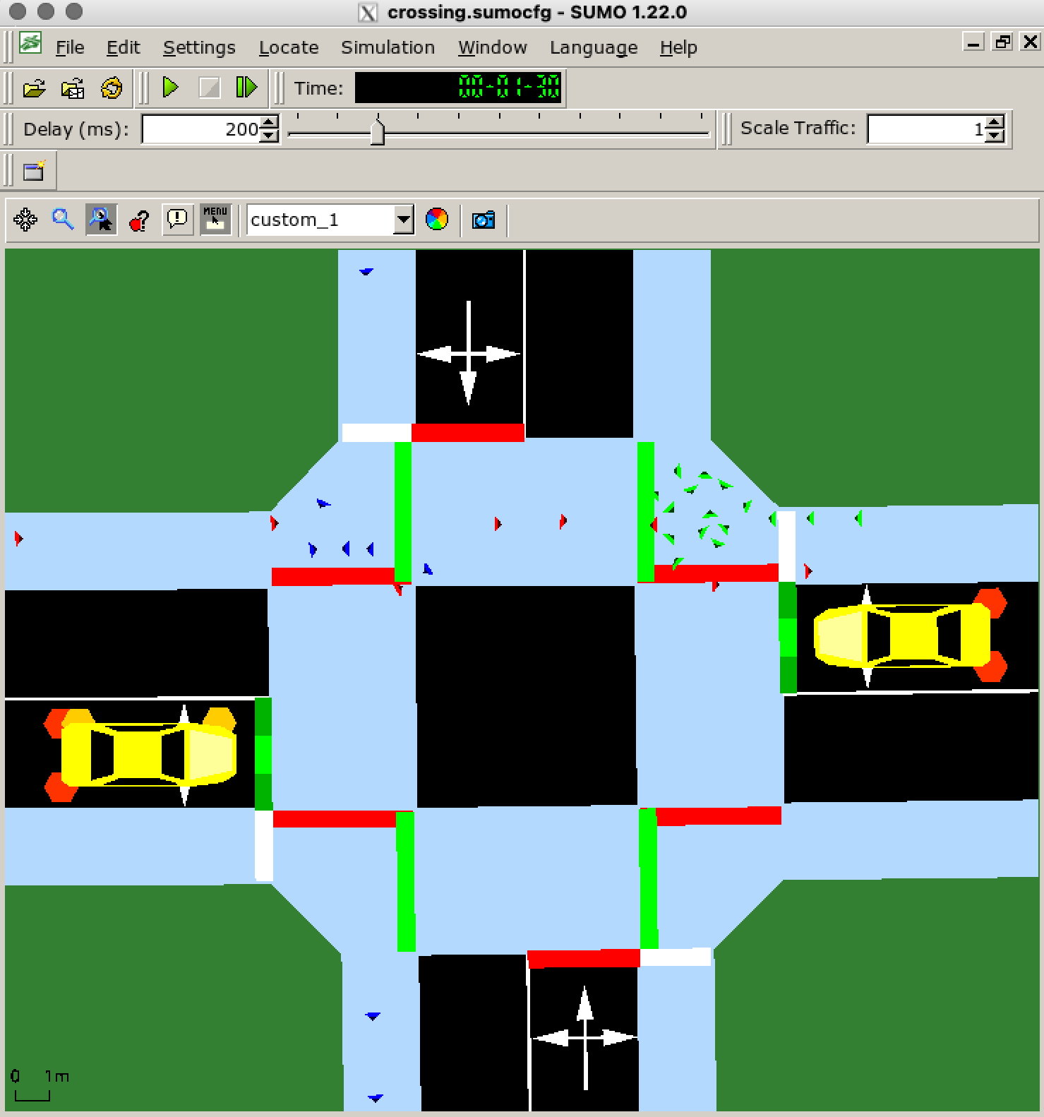
When zooming in you can see interacting cars and pedestrian at the crossing. For this simulation the striping model is used. As you can see the pedestrians are moving and waiting in structured formations.
Run with JuPedSim Model#
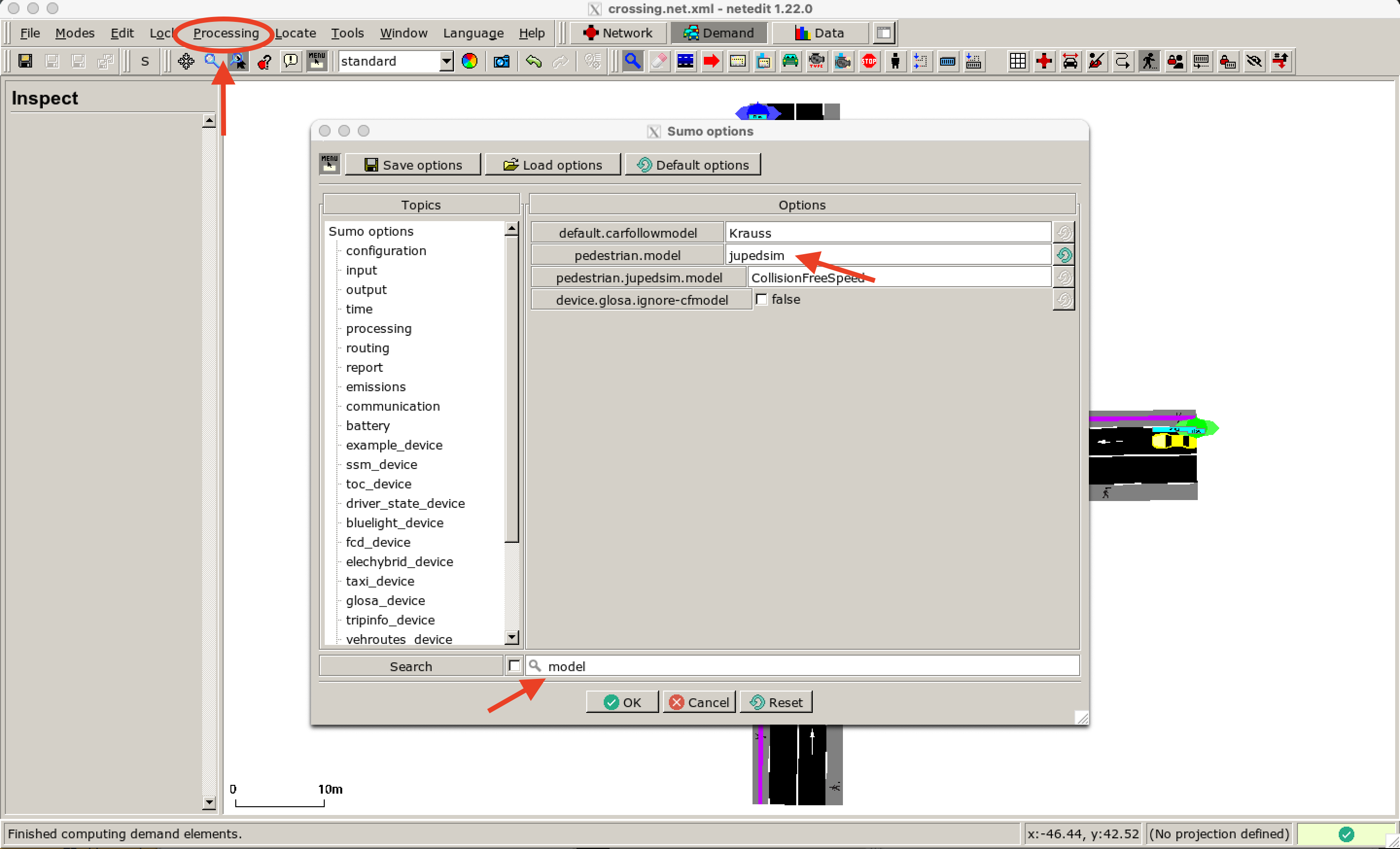
Now we want to use the JupedSim model instead. For this, we open nededit again and change the configuration options by clicking on Processing > Sumo options. An new window is opened. Search for model and type in jupedsim as a pedestrian model.
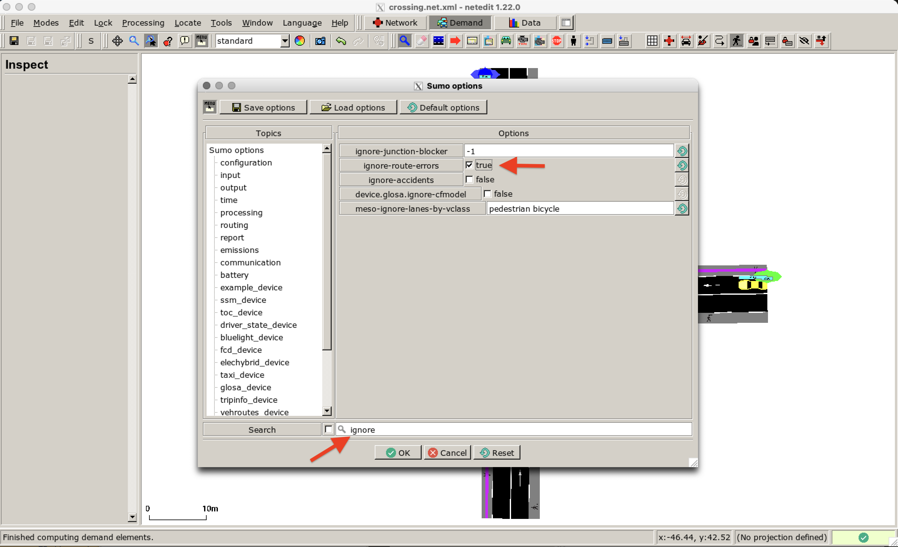
The JuPedSim routing differs from the usual SUMO routing. Edges within the walkable area do not necessarily have to be connected to each other. Therefore, we ignore route errors. Enable this function as shown here:
Press OK, save the sumoconfig file and open the simulation scenario in sumo-gui again. The walkable area is shown in light blue now. Your simulation should look similar to this one:
Results#
In the following, you can see a comparison of the two simulations results (left: striping model, right: JuPedSim model). There are clear differences in the movement patterns and interactions as the JuPedSim pedestrians are moving in 2D space.
 |
 |
|---|---|