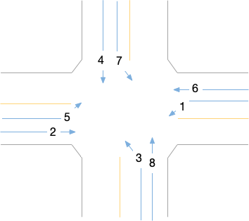
The controller modules in Traffic Lights use a stage-based control structure. A phase is defined as a stage of all allowed movements at a time instance. However, traffic signal controllers used in North America widely use National Electrical Manufacturers Association (NEMA) phase definition. A NEMA phase is defined by a certain flow movement at an intersection. At one time, more than one NEMA phase could happen together as long as they do not conflict with each other.

Example: The movements at an intersection are numbered. The right turns usually go with the associated through movements. The left turn movements are usually odd numbers and the through and right turn movements are usually labeled with even number. Phase 2 and 6 are usually on the main street. An intersection does not need to have all 8 phases.
SUMO now includes a controller module that is compatible with NEMA phases. The NEMA-phase controller can perform actuated or coordinated actuated control. This module is developed by Tianxin Li and Qichao Wang at the National Renewable Energy Laboratory and funded by U.S. Department of Energy Vehicle Technology Office.
NEMA Phases#
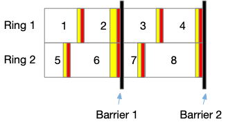
We can visualize the NEMA phases and timings in Ring-and-Barrier structured NEMA diagrams. For one controller, only one phase from a ring can be activated at a time. Phases from different rings could be activated together as long as they are not from the different sides of a barrier. When a controller is operated in fixed-time control mode, we can model the NEMA phase timing as a corresponding stage-based control timing without any issues. When introducing actuation into the signal control, a Ring-and-Barrier structured traffic signal controller can be more flexible than stage-based controller by allowing different possible phase combinations.

Example: In the above NEMA diagram, we could see phase 1+5, 1+6, 2+6, 3+7, 3+8 and 4+8. However, when the traffic on phase 1 is very low and phase 1 could gap out early. In that case, we will not see phase 1+6 but additionally see phase 2+5.
Defining New NEMA phase timings#
You can load new definitions for NEMA-phase traffic controller as a part of an additional-file. The signal timing could be updated in simulation through TraCI functions. A definition of a traffic light program for a four-leg eight-phase intersection within an additional-file looks like this:
<add>
    <tlLogic id="2881" offset="10" programID="NEMA" type="NEMA">
        <param key="detector-length" value="20"/>
        <param key="detector-length-leftTurnLane" value="10"/>
        <param key="total-cycle-length" value="130"/>
        <param key="ring1" value="1,2,3,4"/>
        <param key="ring2" value="5,6,7,8"/>
        <param key="barrierPhases" value="2,6"/>
        <param key="coordinate-mode" value="true"/>
        <param key="barrier2Phases" value="4,8"/>
        <param key="minRecall" value="2,6"/>
        <param key="maxRecall" value=""/>
        <param key="whetherOutputState" value="true"/>
        <param key="fixForceOff" value="false"/>
        <phase duration="99" minDur="5"  maxDur="25" vehext="2" yellow="3" red="2" name="3" state="rrrrrrrrGrrr"/>
        <phase duration="99" minDur="5"  maxDur="25" vehext="2" yellow="3" red="2" name="7" state="rrGrrrrrrrrr"/>
        <phase duration="99" minDur="5" maxDur="30" vehext="2" yellow="3" red="2" name="4" state="GGrrrrrrrrrr"/>
        <phase duration="99" minDur="5" maxDur="30" vehext="2" yellow="3" red="2" name="8" state="rrrrrrGGrrrr"/>
        <phase duration="99" minDur="5"  maxDur="20" vehext="2" yellow="3" red="2" name="1" state="rrrrrGrrrrrr"/>
        <phase duration="99" minDur="5"  maxDur="20" vehext="2" yellow="3" red="2" name="5" state="rrrrrrrrrrrG"/>
        <phase duration="99" minDur="5"  maxDur="35" vehext="2" yellow="3" red="2" name="2" state="rrrrrrrrrGGr"/>
        <phase duration="99" minDur="5"  maxDur="35" vehext="2" yellow="3" red="2" name="6" state="rrrGGrrrrrrr"/>
    </tlLogic>
</add>
For an intersection at a ramp, the traffic light program configuration could look like this:
<add>
    <tlLogic id="2881" offset="10" programID="NEMA" type="NEMA">
        <param key="detector-length" value="20"/>
        <param key="detector-length-leftTurnLane" value="10"/>
        <param key="total-cycle-length" value="120"/>
        <param key="ring1" value="1,2,0,4"/>
        <param key="ring2" value="0,6,0,4"/>
        <param key="barrierPhases" value="2,6"/>
        <param key="coordinate-mode" value="true"/>
        <param key="barrier2Phases" value="4,4"/>
        <param key="minRecall" value="2,6"/>
        <param key="maxRecall" value=""/>
        <param key="whetherOutputState" value="true"/>
        <param key="fixForceOff" value="false"/>

        <phase duration="99" minDur="6"  maxDur="16" vehext="2" yellow="4" red="1" name="1" state="srrrrrrGGrrr"/>
        <phase duration="99" minDur="10" maxDur="67" vehext="2" yellow="4" red="1" name="2" state="srrrrrrrrGGG"/>
        <phase duration="99" minDur="10" maxDur="22" vehext="2" yellow="3.5" red="1.5" name="4" state="GGGGGrrrrrrr"/>
        <phase duration="99" minDur="10" maxDur="88" vehext="2" yellow="4" red="1" name="6" state="srrrrGGrrrrr"/>
    </tlLogic>
</add>

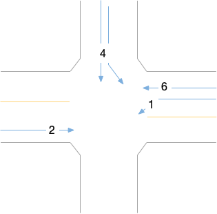
Example: A ramp intersection which only has phases 1, 2, 4, and 6. Phase 4 controls the traffic from the off ramp.
<tlLogic> Attributes#
The following attributes/elements are used within the tlLogic element:
| Attribute Name | Value Type | Description |
|---|---|---|
| id | id (string) | The id of the traffic light. This must be an existing traffic light id in the .net.xml file. Typically the id for a traffic light is identical with the junction id. The name may be obtained by right-clicking the red/green bars in front of a controlled intersection. |
| type | NEMA (string) | This value should be kept as NEMA to activate the NEMA-phase controller module |
| programID | id (string) | The id of the traffic light program. |
| offset | int | The offset value in seconds. Default to 0. Only effective when the controller is in coordinated mode. The reference to the offset is dependent on the controller cabinent type, which is configured via the cabinentType parameter below. |
<param> Attributes#
The following parameters are used to set the NEMA diagram and controller behavior:
| Parameter Key | Value Type | Description |
|---|---|---|
| detector-length | int | The length (in meters) of the stop bar detectors for non-left-turn lane. Note that the detectors can be replaced by customized detectors. This parameter is for quick generation of a stop bar detector setting. |
| detector-length-leftTurnLane | int | The length (in meters) of the stop bar detectors for left-turn lane. Note that the detectors can be replaced by customized detectors. This parameter is for quick generation of a stop bar detector setting. We have this parameter here because typically the stop bar detectors on the left-turn lanes have different lengths from the through lanes. |
| total-cycle-length | int | The cycle length in seconds. |
| ring1 | string | The phase numbers in ring 1 separated by comma (','). Fill 0 if a phase does not exist. |
| ring2 | string | The phase numbers in ring 2 separated by comma (','). Fill 0 if a phase does not exist. Repeat the ring 1 phases of the side of barrier if that side of barrier does not have any phases. |
| barrierPhases | string | One set of phases, separated by comma (','), that need to end together. This defines a barrier. Usually phase 4 and 8, i.e., "4,8". |
| coordinate-mode | bool (true or false) | Default to false. True if the controller is in coordinated mode. |
| barrier2Phases | string | One set of phases, separated by comma (','), that need to end together. This defines another barrier. If in coordinated mode, this set of phases are the coordinated phases. Usually phase 2 and 6, i.e., "2,6". |
| minRecall | string | One set of phases, separated by comma (','), that will get activated no matter if the corresponding detectors will be activated or not. The duration of the phase activation will be between minDur and maxDur of the phase. E.g., "2,6". The value will be default to "1,2,3,4,5,6,7,8" if not set (all the existing phases will be called). |
| maxRecall | string | One set of phases, separated by comma (','), that will get activated no matter if the corresponding detectors will be activated or not. The duration of the phase activation will be the maxDur of the phase. If you set all the phases to have maxRecall, the controller will behave as a fixed time controller with the green times being the maxDur of the phases. The value will be default to empty ("") if not set. |
| fixForceOff | bool (true or false) | If true, the controller will be in fixed force-off mode. This permits non-coordinated phases to use the unused time of previous phases. If false, the controller will be in floating force-off mode. default false |
| whetherOutputState | bool (true or false) | Whether record the signal phase change events. This could be used for generating Automated Traffic Signal Performance Measures (ATSPM). The value will be default to false if not set. |
| show-detectors | bool (true or false) | It controls whether generated detectors will be visible or hidden in sumo-gui. The default for all traffic lights can be set with option --tls.actuated.show-detectors. It is also possible to toggle this value from within the GUI by right-clicking on a traffic light. |
| controllerType | string (TS2 or Type 170) | It controls the type of controller used. NEMA TS2 controllers reference the coordinated offset to the beginning of the 1st coordinated phase. Type 170 controllers reference the coordinated offset to the beginning of yellow on the coordinated phase. TS2 offset has been validated against software-in-the-loop Econolite controllers. default TS2. |
| latchingDetectors | string | Passing a string of phases (like "1,2,3,4") will cause the detector in those phases to remain on until the phase has been served, regardless of whether the vehicle left the detection zone or not. default "". |
| crossPhaseSwitching:X | string | X is a phase number. For example, key="crossPhaseSwitching:2" value="5" will cause phase 5 detector to report to phase 2 while phase 2 is active. Default is no cross phase switching |
<phase> Attributes#
Each phase is defined using the following attributes:
| Attribute Name | Value Type | Description |
|---|---|---|
| duration | time (int) | This attribute is default to 99 and does not affect the control. The duration of the phase will change dynamically according to the traffic actuation and constrained by minDur and maxDur. |
| minDur | time (double) | The minimum green of the phase. |
| maxDur | time (double) | The maximum green of the phase. In coordinated mode, it's the split minus the yellow and all red time of the phase. |
| vehExt | time (double) | Vehicle extension in seconds of the actuated phase. |
| yellow | time (double) | The yellow time of the phase. |
| red | time (double) | Red clearance time of the phase. |
| name | int | The NEMA phase number. |
| state | string | The state attribute defines the allowable movements associated with the phase. This is best set from netedit. You can find more information from Traffic Lights -> Signal state definitions |
Change the timings during the simulation#
Certain signal timing parameters can be updated during the simulation through TraCI.
- traci.trafficlight.setNemaOffset(tlsID, offset): The offset will be adjusted by shortening or extending the green time of the coordinated phase so that the end of the coordinated phase will match the offset. It is recommended to change the offset gradually to mimic a transition time.
- traci.trafficlight.setNemaMaxGreens(tlsID, maxGreens): sets maximum green times for each NEMA phase by giving 8 numbers. Time 0 must be used for each phase that does not exists
- traci.trafficlight.setNemaSplits(tlsID, splits): works like setNemaMaxGreens but subtracts the red- and yellow-times before setting maximum green time for each phase
- traci.trafficlight.setNemaCycleLength(tlsID, cycleLength): the cycle length may change when you update the splits/max green. You need to set the new cycle length to make the new timing work without problems.
All the updates in the signal timing parameters in the NEMA-phase controller will happen after the current cycle ended.
Configuration Errors#
The following errors may be raised:
- the phases before barrier X from both rings do not add up: EXPLANATION FORTHCOMING
- Ring X does not add to cycle length: EXPLANATION FORTHCOMING
To simulate misconfigured controllers, both errors may be ignored by setting <param key="ignore-errors" value="true"/>.
Publication#
The implementation and validation of the controller was described in Schrader, M.; Wang, Q.; Bittle, J. Extension and Validation of NEMA-Style Dual-Ring Controller in SUMO. SUMO Conf Proc 2022, 3, 1-13.
